
FZG/CX-12/630 Outdoor Loadbreak Tool
►INTRODUCTION
FZG/CX-12/630 outdoor loadbreak tool – unlike loadbreak cutouts or hookstick-operated interrupter switches - design to be light in weight and high portability high voltage loadbreak interrupter. It brings load switching capability through 12 kV and 50Hz to your overhead distribution system, such as disconnect, cutout, power fuse, fuse limiter, and dropout recloser.
►OPERATING SPECIFICATION
1. Working Condition
1)Ambient Air Temperature: -40oC~+40oC
2)Altitude Height: 1000m
3)Outdoor environmental condition: Sunny and relative humidity with ≤70%
2. Technical Specifications

►CHARACTERISTICS
1. Simple to operate
2. Easy to operate and great flexibility
3. High stability
4. Long operating life
5. Suitable for switching disconnect, cutout, power fuse, fuse limiter and dropout recloser.
►MAIN STRUCTURE AND WORKING PRINCIPLE
1. Main Structure
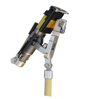
The Product’s exterior configuration is shown in Figure 1. It is composed by vacuum arc extinguish chamber, operation anchor, pull-ring hook and energy storage trailer. The product materials are mainly used of Al-alloy, Ti-alloy and ABS that is light weighted and non-fragile.

Figure 1. FZG/CX-12/630 outdoor loadbreak tool configuration
To adapt for different products and different installation systems, the operation anchor is designed to be rotatable with main body at 30 degree. The Benn structure is applied on the tip of operation anchor, which can be reliably connected to the switch, and easy to connect and release.
For the energy storage trailer, the storage process can be simply complete by thrusting 30 degree away from the main body.
2. Working Principle
FZG/CX-12/630 outdoor loadbreak tool is installed on the tip of the universal pole. Under the energy storage condition, engage pull-ring hook on the pull-ring of the blade or fuse tube. As the universal pole is pulled downward with a firm, steady stroke- and the tool is extended to its maximum length-the trigger inside the tool trips, the stationary contact of vacuum arc extinguish chamber is separated. When the vacuum arc extinguish chamber is not separated, the current is diverted through the extinguish chamber where an isolating gap is established. The resetting latch retains the tool in this open position until released to reset the loadbreak tool for its next operation.
►APPLICATIONS
1. Assembly and Operation
There are two parts in the FZG/CX-12/630 outdoor loadbreak tool package, which are the loadbreak tool and universal pole. The universal pole is divided into three parts. The loadbreak tool is connected with the universal pole by M8 screw. There are three different connecting slut can be chose depends on different operation angles. Under the common condition, the middle connecting slut is mostly used, which is shown in Figure 1. For each part of the universal pole, they are connected by screw thread. Each screw thread must be securely attached in the assembly process and check flexibility of the loadbreak tool part, and then starting energy storage process. The energy storage process is shown as following steps: hold the energy storage trailer and thrust the energy storage handle about 30 degree away from the main body until hearing a “click” sound, while the arm obviously feels the counterforce is getting smaller. At this point, the energy storage process is completed.
There are two parts in the FZG/CX-12/630 outdoor loadbreak tool package, which are the loadbreak tool and universal pole. The universal pole is divided into three parts. The loadbreak tool is connected with the universal pole by M8 screw. There are three different connecting slut can be chose depends on different operation angles. Under the common condition, the middle connecting slut is mostly used, which is shown in Figure 1. For each part of the universal pole, they are connected by screw thread. Each screw thread must be securely attached in the assembly process and check flexibility of the loadbreak tool part, and then starting energy storage process. The energy storage process is shown as following steps: hold the energy storage trailer and thrust the energy storage handle about 30 degree away from the main body until hearing a “click” sound, while the arm obviously feels the counterforce is getting smaller. At this point, the energy storage process is completed.
FZG/CX-12/630 outdoor loadbreak tool can be operated either on boom lift or by safety harness, as shown in Figure 2. When using a boom lift, the operator must stay away from HV cable. The proper operation process is shown as follows: the loadbreak tool with the universal pole must across the front of the device (open disconnects, cutouts, power fuses, fuse limiters, and dropout reclosers) and attach loadbreak tool’s anchor to the attachment hook on the far side (Figure 3), which is easy for observation and operation. Otherwise, it will block the sight and be difficult to detach from the device due to the tool distortion.
When the loadbreak tool is properly hook on the device as shown in Figure 3, firmly pull the universal pole. At this time, the device is open where the current is diverted through the tool. As continuously pull the universal pole downward, appearing a “click” sound-and the tool is extended to certain length. At this time, the current has been cut off and follow by removing its anchor from the device’s attachment hook (it needs to pay special attention to the open position to keep sufficient insulation distance). Then, Reset the tool by releasing the resetting latch and firmly close the tool to its fully telescoped position (Figure 1) - and then storage energy again ready for the next operation.

Figure 2. Operation on the (a) boom lift or by (b) safety harness

Figure 3. The Loadbreak tool is attached on the device
2. Operation Precaution
The loadbreak tool must be energy stored for each operation, and confirm that the stationary contact of vacuum arc extinguish chamber has been closed. What if to disconnect load current with the stationary contact of vacuum are extinguish chamber is separated, it will cause arcing, burning device and may hurt the operator.
The loadbreak tool must be energy stored for each operation, and confirm that the stationary contact of vacuum arc extinguish chamber has been closed. What if to disconnect load current with the stationary contact of vacuum are extinguish chamber is separated, it will cause arcing, burning device and may hurt the operator.
In order to maintain self-sustaining pressure for stationary contact of vacuum arc extinguish chamber, it is required to be in energy stored condition when the tool is not using. Once the tool is plan to used, manually open/close the tool several times and make sure it works properly. Then, it can be performed at the scene of application.
The loadbreak tool is assembled with the universal pole which contains three separated parts. When selecting a disconnect to be switched by the tool, all three separated parts must be securely screwed and prohibit to use one or two of them.

Figure 4. Switching a disconnect

Figure 5. Switching a CX Dropout Sectionalizer

Figure 6. Switching a power fuse
3. Qualities required for operators
The operators of the FZG/CX-12/630 outdoor loadbreak tool must be trained with knowledge of safety operation as follows:
(a) Must have the ability and skills to recognize the live parts from the currentless parts.
(b) Must have the ability and skills to maintain appropriate safe distance with the high-voltage energy.
(c) Must have the ability and skills to use proper protective equipments when working closer the exposed parts of electrical equipment, such as insulation/shielding materials and insulation tools.
The purpose of this instruction manual is not intended to replace those who have safety knowledge and experience about electrical equipments; on the contrary it is to guide these people have more ability to work better. Therefore, the operators must carefully read the instruction manual before the operation.
►Enclosed operation notice illustration
1. The Figure shows the connection between the Loadbreak and the special insulation operation rod. Place the two groove centered and hand-tighten with the screw. The insulation operation rod must be fully connected with three sections before operating.

2. Each time before the operation or long-term when not in use should be to the operation of the tool storage, the method as shown in figure, energy storage rod push back angle of 55 degrees can be stored energy.

3. The end of the tool is operated at the fixed end of the switch, and the operating hook is hooked to the movable contact end of the operated switch.

4. Firmly pull the universal pole. At this time, the device is open where the current is diverted through the tool. As continuously pull the universal pole downward, appearing a “click” sound-and the tool is extended to certain length. At this time, the current has been cut off and follow by removing its anchor from the device’s attachment hook.

5. Reset the tool by releasing the resetting latch and firmly close the tool to its fully telescoped position - and then storage energy again ready for the next operation.
